

Dicing blades may look simple, but in semiconductor manufacturing, small differences in blade construction can have a significant impact on yield, cutting performance, and process cost.
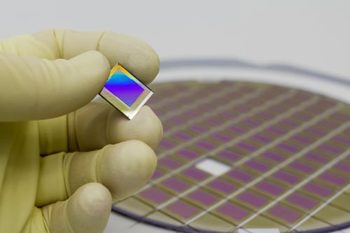
Diamond dicing blades are used to singulate silicon wafers and cut materials including sapphire, GaAs, SiC, glass, and technical ceramics. They are also used in advance dicing and packaging applications where precise cuts are required through semiconductor materials, molding compounds, and package structures.
Because many of these materials are hard, brittle, or both, the dicing process must remove material without allowing fractures to extend into the finished die. Chipping, cracking, blade deflection, and inconsistent kerf can quickly turn a tooling problem into a yield problem.
Selecting the right dicing blade therefore requires more than choosing the correct diameter and thickness. Blade structure, bond type, diamond grit, concentration, blade exposure, spindle speed, feed rate, coolant delivery, and substrate material all influence performance.
Understanding those variables is the first step toward developing a more stable dicing process.
What a Diamond Dicing Blade Does and Why Selection Matters
To understand why selection matters so much, it helps to start with what the blade is actually doing during the cut.
The Role of Dicing Blades in Wafer Singulation
Wafer dicing is the process of separating a processed wafer into individual dies or chips.
A thin diamond blade rotates at high spindle speed while traveling along predefined streets between devices. The diamond abrasive removes material at the blade's cutting edge through a precision grinding action, creating a narrow kerf through the wafer or package.
The basic process sounds straightforward. The tolerances are not.
The blade must remain stable while producing a narrow, consistent cut without introducing excessive chipping or subsurface damage into adjacent dies.
As die sizes decrease and device density increases, the amount of material available between devices can also become more limited. Kerf control and blade stability therefore become increasingly important.
How the Wrong Blade Affects Yield and Process Cost
A blade can successfully cut through a wafer and still be the wrong blade for the process.
Poor blade selection may result in:
- Excessive front- or backside chipping
- Cracking
- Blade loading
- Blade deflection
- Inconsistent kerf width
- Poor cut straightness
- Excessive blade wear
- Reduced feed rates
- Frequent blade changes
These problems affect more than blade cost.
If a blade forces the process to run slower, creates additional rejected dies, or requires frequent replacement, the lowest-priced blade may produce the highest overall cost per wafer.
Hubbed Versus Hubless Dicing Blades
Before bond type or grit even enter the conversation, blade structure is usually the first fork in the road.
How Blade Structure Affects Rigidity and Precision
One of the first decisions is whether the application requires a hubbed or hubless blade.
A hubbed dicing blade incorporates the cutting blade and hub into an integrated assembly. The hub supports the thin cutting section and provides a controlled mounting interface.
This additional support can improve rigidity and simplify mounting in compatible dicing systems.
A hubless blade is an extremely thin circular blade without an integrated hub. It is mounted between precision flanges on the dicing saw spindle.
Hubless construction provides greater flexibility in blade dimensions and can support very thin cutting widths, but correct mounting becomes particularly important. Flange condition, cleanliness, alignment, and runout all influence blade stability.
Choosing Between Hubbed and Hubless for Your Dicing Saw
The machine itself is the first consideration.
Dicing saws are designed around specific spindle and mounting configurations, so hubbed and hubless blades are not necessarily interchangeable.
Beyond machine compatibility, engineers should consider blade thickness, exposure, cut depth, substrate, required kerf, spindle speed, and rigidity.
A very thin blade may reduce kerf but becomes increasingly sensitive to lateral forces and deflection.
The objective isn't simply to use the thinnest possible blade.
It is to use the thinnest blade that remains sufficiently stable for the required cut.
Dicing Blade Bond Types
Once blade structure is settled, bond type becomes the next major factor shaping how the blade actually cuts.
Resin Bond Blades for Free-Cutting Performance
Resin-bond dicing blades hold diamond abrasive within an organic bond matrix.
One of their primary advantages is the ability to engineer the bond for relatively free-cutting behavior. As the bond wears, fresh diamond can become exposed, helping the blade maintain cutting action.
This can be valuable when cutting brittle materials where excessive cutting force contributes to chipping.
Resin bond blades can be used across materials including silicon, glass, quartz, sapphire, ceramics, and other hard or brittle substrates, depending on the specific blade formulation.
The tradeoff is that a freer-cutting bond may wear more quickly than a more wear-resistant bond.
Again, maximum blade life isn't always the objective. A blade that wears predictably while maintaining excellent cut quality may be economically preferable to one that lasts longer but progressively loses cutting performance.
Nickel Bond Blades for Thin, Precise Cutting
Nickel-bond diamond blades are commonly produced through an electroforming or related deposition process that holds diamond within a nickel matrix.
This construction can produce extremely thin, precise blades with strong diamond retention.
Nickel-bond blades can be manufactured in hubbed and hubless configurations and are used for materials including silicon, GaAs, sapphire, and other semiconductor or technical substrates.
Their dimensional stability and thin-kerf capability make them attractive for applications where valuable wafer area must be preserved.
However, diamond exposure and bond behavior still need to match the material. Strong abrasive retention is useful only if the blade continues cutting efficiently.
Sintered Metal Bond Blades for Wear Resistance
Sintered blades use diamond distributed through a metal bond matrix rather than relying on a single abrasive layer.
As the blade wears, additional abrasive can become exposed.
This multi-layer construction can provide excellent durability and make sintered metal bond blades useful where extended blade life and stable geometry are important.
The tradeoff is that bond strength, diamond exposure, and cutting forces must still be matched to the substrate.
No bond type is automatically best simply because it lasts longer.
Matching Blade Type to Substrate Material
Bond type only tells part of the story; the substrate itself plays just as large a role in blade selection.
Dicing Silicon Wafers
Silicon is one of the most established wafer-dicing applications, but that doesn't make blade selection trivial.
Silicon is brittle enough that poor blade condition, excessive feed, incorrect grit, or unstable cutting can produce edge chipping and subsurface damage.
Blade selection depends on wafer thickness, street width, die dimensions, acceptable chipping, dicing tape or mounting system, cut depth, and production requirements.
Both resin and nickel-based blade systems can be used depending on the specific process.
Dicing Sapphire and Compound Semiconductor Substrates Like GaAs
Sapphire, GaAs, SiC, and other specialty semiconductor substrates introduce different cutting challenges.
Sapphire and SiC are exceptionally hard and wear-resistant. GaAs, while not as hard as sapphire or SiC, is brittle and can be particularly susceptible to edge fracture and backside chipping.
These differences mean that a blade specification qualified for silicon shouldn't automatically be transferred to another semiconductor substrate.
Diamond grit, bond, blade thickness, feed, spindle speed, and cut strategy may all need to change.
Why Hard and Brittle Materials Require Different Blade Specifications
Hardness alone doesn't determine dicing behavior.
Fracture toughness, crystal structure, wafer thickness, coatings, metallization, device layers, and mounting conditions also influence how a substrate responds to the blade.
For this reason, describing all compound semiconductors as simply requiring "slower feeds and finer grit" can be misleading.
Those may be useful adjustments in some processes, but the specification should be developed around the actual substrate and quality requirement.
Blade Specifications That Affect Cutting Performance
Beyond bond and substrate, a handful of core blade specifications directly shape cutting behavior.
Diamond Grit Size and Diamond Concentration
Diamond grit size affects both material removal and cut quality.
Larger diamond particles generally provide more aggressive cutting action and greater chip clearance. However, the larger abrasive interaction can also increase the potential size of brittle fractures.
Finer diamond grit creates smaller individual cutting interactions and can support improved edge quality.
But extremely fine grit isn't automatically better.
If the blade becomes too fine for the stock removal and material, cutting forces may increase as the blade loads or loses free-cutting behavior.
Diamond concentration also influences the number of active cutting points interacting with the substrate.
The ideal combination balances cutting rate, blade wear, edge quality, and process stability.
Blade Thickness and Diamond Exposure
Blade thickness directly influences kerf width.
A thinner blade removes less material, which can help preserve valuable wafer area and potentially allow more usable die from a wafer.
But reducing thickness also reduces blade stiffness.
If the blade becomes unstable, lateral deflection can produce a cut wider than the nominal blade thickness. It can also cause edge damage, poor straightness, or blade failure.
Diamond exposure presents a similar balance.
The blade needs sufficient exposed abrasive to cut efficiently while maintaining enough bond support to hold the diamond securely.
Dicing Process Parameters That Depend on Blade Selection
Even the right blade specification still needs to be paired with the correct process parameters to perform as intended.
Feed Rate and Spindle Speed
Blade specification and process parameters cannot be developed independently.
Feed rate determines how quickly the blade encounters new material. Increasing feed generally increases the material-removal demand on the blade and can increase cutting forces.
Spindle speed affects abrasive engagement and wheel surface speed.
There is no single RPM that is correct for every dicing blade because blade diameter, substrate, bond, grit, feed, and machine capability all matter.
A stable process requires the blade and parameters to be optimized together.
If chipping increases when feed is raised, the answer may be be using slow feed rates—but it may also indicate that the existing blade specification isn't sufficiently free-cutting for the desired production rate.
Coolant Flow Rate and Nozzle Positioning
Coolant is critical in precision dicing.
It removes heat from the blade and substrate while flushing grinding debris from the kerf.
Simply increasing coolant volume isn't enough. The coolant has to reach the blade-workpiece interface effectively and consistently.
Nozzle alignment should direct clean coolant toward the cutting zone and along the blade so that debris is carried away rather than recirculated into the kerf.
Poor coolant delivery can contribute to blade loading, higher cutting temperature, increased chipping, and uneven blade wear.
Common Dicing Challenges and Their Blade-Related Causes
When these variables aren't properly aligned, a handful of recurring problems tend to show up on the production floor.
Chipping and Edge Damage During Singulation
Chipping occurs when fractures created during abrasive cutting extend beyond the intended kerf.
Blade grit, blade edge condition, feed rate, cut depth, spindle speed, substrate support, and the material itself can all affect chipping.
Cut strategy can matter just as much as blade specification.
A documented study involving 100 μm-thick silicon wafers laminated with die-attach film found that an alternative double-pass sawing process reduced chip/lateral cracking by almost 80% compared with a conventional single-pass process. The researchers attributed the improvement to reduced blade loading and a better-controlled separation process.
The result shouldn't be interpreted as meaning double-pass dicing always reduces chipping by 80%. The experiment involved a specific thin-wafer and DAF configuration.
It does demonstrate an important principle:
Even the correct blade can underperform if the cutting strategy puts excessive mechanical load on a brittle wafer.
For some difficult substrates or thicker sections, step cutting or multiple-pass strategies can therefore be evaluated alongside changes in blade specification.
Blade Deflection and Wobble
A thin dicing blade is inherently sensitive to lateral forces.
Excessive feed, improper flange mounting, spindle runout, excessive blade exposure, or insufficient blade stiffness can cause deflection.
The result may be:
- Wider or inconsistent kerf
- Wandering blade cuts
- Increased side chipping
- Poor die dimensions
- Uneven blade wear
When these symptoms appear, simply changing grit may not solve the problem.
Machine condition, mounting, blade thickness, exposure, and operating parameters should all be evaluated.
Advanced Packaging Applications and Blade Selection
These challenges become even more pronounced once dicing moves beyond bare wafers into advanced packaging.
Dicing Requirements for QFN and BGA Packages
Dicing isn't limited to bare semiconductor wafers.
Advanced packaging applications such as QFN (quad flat no-lead) and BGA can require cutting through combinations of molding compound, resin, metal features, substrate materials, and other layers.
That creates a very different cutting environment from a homogeneous silicon wafer.
The blade may need to maintain cutting performance while transitioning through materials with very different hardness, ductility, and loading behavior.
Bond selection becomes particularly important because the blade needs enough abrasive exposure to avoid loading while maintaining the geometry required for narrow, controlled cuts.
Why Advanced Packaging Demands Tighter Blade Control
As package geometries become smaller and streets narrower, variation in blade thickness, runout, wear, and cutting behavior becomes increasingly significant.
Blade consistency across production lots also matters.
Once a process has been qualified, changes in bond behavior, diamond distribution, blade thickness, or blade geometry can affect the established cutting parameters.
A production dicing blade therefore needs to be reproducible—not merely capable of producing one successful test cut.
How to Choose the Right Dicing Blade for Your Application
With all of these variables in mind, choosing the right blade ultimately starts with defining the application itself.
Matching Bond Type and Grit to Your Substrate and Process
The right dicing blade specification begins with the dicing application rather than the blade catalog.
Process engineers should establish:
- Substrate material
- Wafer or package thickness
- Required kerf
- Street width
- Acceptable front- and backside chipping
- Blade diameter
- Blade thickness
- Cut depth
- Spindle speed
- Feed rate
- Coolant delivery
- Production volume
- Current blade life
- Existing process problems
From there, bond type, grit, concentration, blade structure, and thickness can be selected around the actual manufacturing objective.
A blade optimized for maximum life may not produce the best edge quality. A blade optimized for an extremely narrow kerf may not provide sufficient rigidity for a deep cut.
The correct specification balances these competing requirements.
Working With an Application Engineer for a Custom Blade Specification
No single dicing blade specification works across silicon, GaAs, sapphire, SiC, ceramics, glass, and advanced semiconductor packages.
That is why working directly with an application engineer can be more effective than selecting a blade from dimensions alone.
Substrate hardness and brittleness, wafer thickness, die size, street width, machine configuration, production volume, and acceptable chipping all influence the ideal combination of bond, grit, concentration, and blade thickness.
For a closer look at this approach, see Eagle Superabrasives' guide to application-specific slicing and dicing wheels, including wheel selection for silicon wafers, ceramics, glass, and other precision materials.
Let Eagle Superabrasives Help You Select the Right Dicing Blade
Dicing blades should not be treated as interchangeable consumables.
Blade structure determines rigidity and mounting behavior. Bond type controls how diamond is held and exposed. Grit affects cutting action and edge quality. Blade thickness influences both kerf and stability. Feed, spindle speed, and coolant determine how that blade actually performs once it enters production.
Those variables ultimately affect yield, throughput, blade life, and cost per finished die.
The best dicing process therefore isn't necessarily the one using the longest-lasting blade, the thinnest blade, or the fastest feed rate.
It is the entire dicing process that consistently produces acceptable dies at the lowest total manufacturing cost.
Eagle Superabrasives works with manufacturers to develop slicing and dicing blade specifications around the substrate, equipment, dimensional requirements, and production process—helping customers move beyond simply purchasing a blade toward engineering a more stable and repeatable dicing operation.
Reach out to Eagle Superabrasives to work with an application engineer on a blade specification built for your substrate.